The layout doesn't look as an automatic one and becomes even ... esthetic, all in curves.
Back to home page
Back to audio electronics page
The american manufacturer MG Chemicals gives several interesting informations:
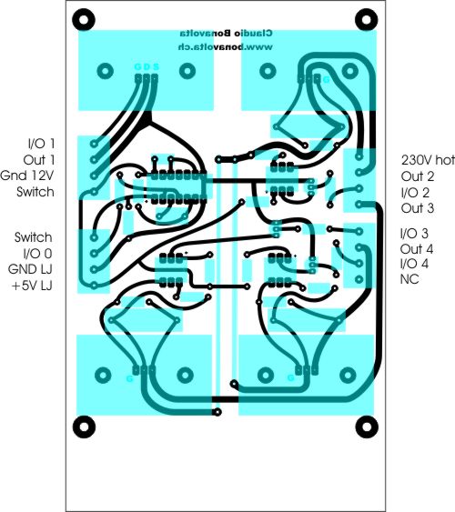
I draw it, with components positioning, under Corel Draw or any other vector software (Adobe Illustrator, etc ...):
The layout doesn't look as an automatic one and becomes even ... esthetic, all in curves.
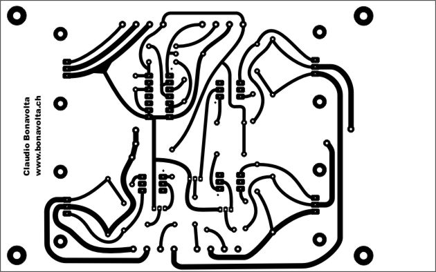
I make a mirror copy of which I remove the silhouettes of the components to keep only the layout of the copper:
The layout is simply printed with a laser on a transparency sheet for lasers and copiers.
The layout is not absolutely opaque but is dark enough for a prototype.
For "production" masks, I reproduce photographically the mask onto an
orthochromatic lith film (Ilford Ortho Plus) with gives a very opaque draft.
I use presensitized board which allows a very precise layout of the tracks.
You have to remove the protective sheet, position the mask on the board and
cover the sandwich with
a thin glass plate (glass of small photo framework, by example).
For the exposure itself, I use two bulbs Osram Nitraphot S of 250W each, at a distance of 43cm (center of the bulb to the
board) switched on for 3 minutes.
Considering the significant production of UV, I avoid remaining in the room during the exposure.
There are small exposure tools using special fluorescent tubes much more practical than this
method.
Such tool can be pretty easily home-made: an example.
Is done in diluted sodium hydroxide at 3%. I replaced it by household
chemicals used to clean sink drains, usually containing sodium hydroxide around
30%, diluted 1+9 to 3% ...
Be cautious with sodium hydroxide as it may cause severe burns (skin, eyes, etc
...), so, wear gloves and eyeglasses.
The exposed parts darkens and tend to be liquified. A soft brush helps to remove
them.
Once done, rinse the board in water.
Chemicals commonly used for etching are:
Ferric Chloride being opaque and the reaction with copper forming a precipitate, I let the board float ,thanks to superficial tension, copper down, in a tray while agitating slowly from time to time. Don't forget to check there is no air bubble trapped below the copper layer !
As Persulfate is transparent and the reaction does not create a precipitate, I let the board sink, copper upside, in the tray and regularly agitate.
I heat the sodium persulfate with a modified aquarium heater able to reach 50°C.
You can find acrylic chassis with heater and bubbler that ease these operations. It should be possible to build one with aquarium equipment ...
Nothing special, use drills in good condition and of size adapted to the
components wires diameters.
Drill starting from the copper side and slightly
bevel the components' side to ease their insertion.
Remove the photosensitive resin with a solvent (acetone, ...).
Work in a well ventilated room and avoid breathing solvent fumes.
Clean copper with a slightly abrasive detergent creme, rinse in running water and dry carefully.
Nothing special:
For electrostatic sensitive components, electrically ground the soldering iron or disconnect it the time you solder it.
For SMD components, stick them with a point of adhesive to maintain them in place before soldering.
There are specific products for this job but a solvent like acetone is effective.
Spray the printed board with a special varnish to protect it against oxidation.